Process description
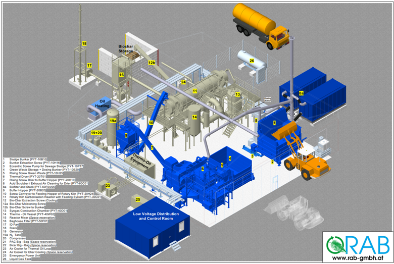
The process of the sewage sludge pyrolysis pilot plant is presented in the figure above and in the text below. The numbers in parentheses in the text refer to the numbers in the above figure.
Reception and storage of sludge and wood material
A wheel loader is used to deliver the sludge from the composting facility to the pilot plant’s steel sludge bunker (1), which is equipped with a lid and exhaust pipe. Wood material (crushed green waste or excess material from compost sifting or wood chips) is delivered to the steel storage bunker (4) by wheel loader.
Thermal drying
The eccentric screw pump (3) is used to pump the sludge from the feeding tray to the thermal dryer (6). A screw conveyor is used to apply the sludge to the feeding end of the thermal dryer. The wood material is transported and applied to the thermal dryer using a screw conveyor.
The thermal dryer has a moving belt onto which the material to be dried is applied at the feeding end of the dryer. The belt carries the material through the “drying furnace”. Partially recycled drying air heated in heat exchangers is blown into the dryer. The necessary heating energy is obtained by combusting the energy-containing gas formed in pyrolysis.
The exhaust air, which contains moisture, is cooled before being led to the acid scrubber (8) and the biofilter (8a) to treat odours. The acid scrubber uses sulphuric acid and produces an ammonium sulphate solution.
The dried sludge-wood mixture is transferred by conveyor to the buffer hopper (9), which is used as buffer storage before feeding to pyrolysis. The sealed buffer hopper has nitration to prevent ignition.
Pyrolysis
The dried sludge-wood mixture is transferred to the pyrolysis unit (11) from the buffer hopper by conveyor. The feeding to pyrolysis occurs through two gate valve joints. The material to be fed is nitrated between the gate valve joints prior to feeding to pyrolysis to minimise the amount of oxygen in the process.
The pyrolysis unit is a rotary kiln in terms of structure. The temperature range of the pyrolysis is designed to be approximately 450–650°C, and the time spent can be adjusted between 30 and 120 minutes. The pyrolysed material is extracted through two gate valve joints, and the material is nitrated in the same way as at the feeding end.
The pyrolysis char is cooled in a conveyor with indirect water cooling (the cooling water circulates within the conveyor jacket). The cooled char is moistened in the next conveyor with either water or ammonium sulphate solution. The finished char product is transferred by conveyor to an outdoor block-structure storage silo.
Combustion of pyrolysis gases
The gases formed in pyrolysis are led directly to combustion (13). The energy from the combustion is utilised in the heating of the pyrolysis unit by leading the flue gases into the jacket of the pyrolysis unit. The residual heat from the flue gases is utilised in drying via thermal oil (14). The thermal oil is heated in a heat exchanger.
Liquefied petroleum gas, which is stored in an outdoor tank, is used as start-up and maintenance fuel in the combustion unit. The maintenance burner is used continuously to keep the combustion process going. The baghouse filter (16) cleans the flue gases from the combustion before they are led to the stack (18).